|
|
 |
Matrix
|
 |
 |
|
|
 All
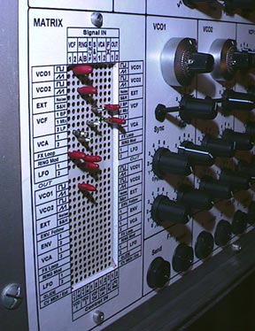
modules are connected to the matrix It is the
heart of the ASM-1X. The
matrix patch and pins come from an old calibration
rack used for planes. It is a Ghielmetti
sized 32x11, 90% filled with goldplated
2mm diodes pins! All
modules are connected to the matrix It is the
heart of the ASM-1X. The
matrix patch and pins come from an old calibration
rack used for planes. It is a Ghielmetti
sized 32x11, 90% filled with goldplated
2mm diodes pins!
Originaly it was a (15+17) rows for 11 columns,
but i have splited it , changing for (15x11)
+ (17x11) with some common rows.The matrix was
easy to open, Swiss made! I have cutted vertical
contacts on middle, and put connectors for columns
of the second half. I have prewired direct connections
betweens rows, columns and buffers. The matrix
is screwed to a structure made of aluminium
corners who shield it.The synth has been builded
all around by adding pcb and aluminium structures.
.Matrix
buffering schematics (gif)
-
Upper matrix is for signal ("audio") , Lower
for controls (CV...).
-
Inputs (Rows = modules output) are
buffered by a classic inverter stage at
unity gain.
-
Outputs (Columns = modules input) are connected
to a classic summing stage (g=1). Connected
pins contain input resistors.
Pins
Modification
For
an analog summing matrix patch, the pin must contain
resitors, not diode. Using
a razor blade,cms solder iron, and lot of patience,
it was finaly possible to replace the diode by
a little CMS resitor without destroying the pin.
Here is the method i use:
-
remove the plastic ( blue or red on my pins)with
cutting-nippers cut the diode side of the
pin approx 0,5cm from top...Destroy the
diode, It doesn't matter.
-
remove with thin pliers,cutter or razor
blade, remaining pieces of the diode
and the metal around it, until you can see
the black plastic isolant and the solder
point of the diode.
-
After a good cleaning of the pin, an isolation
test of the body and top of pin, solder
one side of a 10k CMS resistor.Now
using a little thermotube,isolate the cms
and the solder, exepted the free side
of the resistor.
- Connect
a thin (classic)resistor leg wire from the
body of the pin to the cms resistor and
test with the ohmmeter...
-
Finaly encapsulate the assembly with a kind
of sealing-wax .Not perfect looking , but
works rigth and can be repaired.
|
|
 |
|
 |
|
©
Marc BAREILLE 2002
|


