The Plasma VU-meter display audio levels on Russian bargraph
gaz discharge tubes IN-13
or IN9
First prototypes
Here are pictures and informations about my Plasma VU-meter prototypes most of them were powered by well regulated external hi-voltage
power supply.
The
true- RMS converter stage is inspired from a diy project published into the french electronic
magazine Radio Plans (now disapeared since many years), based on the THAT2252 rms detector chip.
A
THAT2252 chip convert audio levels ( dBs ) into a linear control
voltage ( Volts DC ) to
drive an IN-13 (or IN-9 ) gaz discharge bargraph tubes ... The
THAT2252 is set to provide almost 0V on the output at -20dBu
input level and 2.50V at +20dBu.
An adapted RC time constant set the up/down
raise time to imitate classic vu-meter balistics, The IN-13/IN-9
driver stage is
based on a common LM358 and a hi-voltage power transistor. The full
range display is set by a trimmer.
Download
the Plasma VU-Meter schematic v1.0 (pdf )
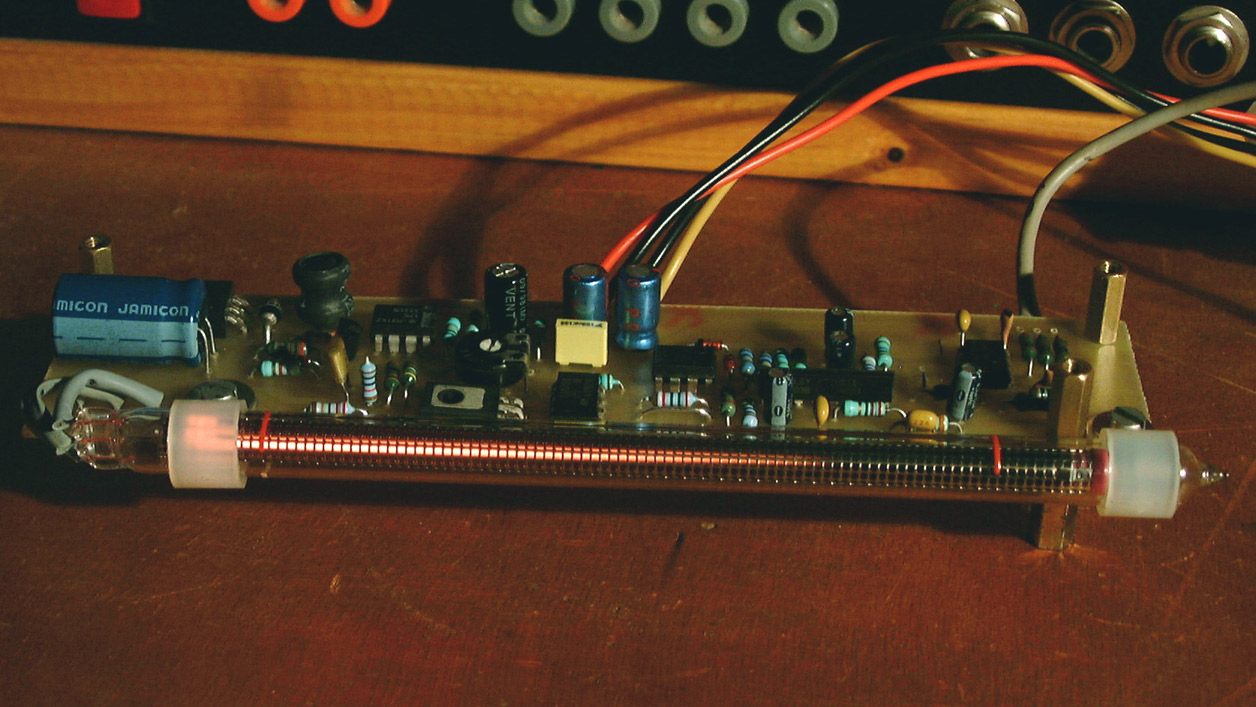
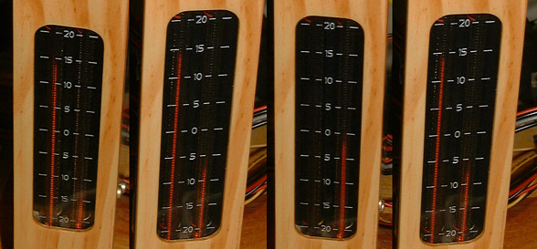
Here are pictures of the VU-meter v1.0 fitted with IN-9 ( purple ) tubes,
both powered with an external hi-voltage psu
 
bellow it is the same... but with IN-13 tubes.
Much more stable and it require at least 2 time less current on the hv-psu
 
Clic
on pictures to view in big
Basic Plasma VU meter +/-20dBU - THAT2252
Features :
- Balanced/unbalanced
input preamp
- Cal/Uncal levels ( +4dBU/-10dBV)
- -20dBU
to +20dBU (If calibrated to 0dB)
- 40 dB range
over 10Hz up to 25kHz bandpass
- True RMS
Levels
- CV output
to use as an enveloppe follower
- Designed to hold IN-13 or IN-9 tubes
- One trimmer for full
range display , hardware calibration
- Stackable
pcb for stereo or multi-track displays
- Integrated
hi-voltage transformless PSU
- Module powered
by +/-15V or +/-12Vdc
Download
the Plasma VU-Meter +/-20dB -That 2252 BOM v2.1 (txt )
Download
the Plasma VU-Meter +/-20dB -That2252 schematic v2.1 (pdf )

The
revision 2.1 pcb is perfect to build mono , stereo or multitrack
displays
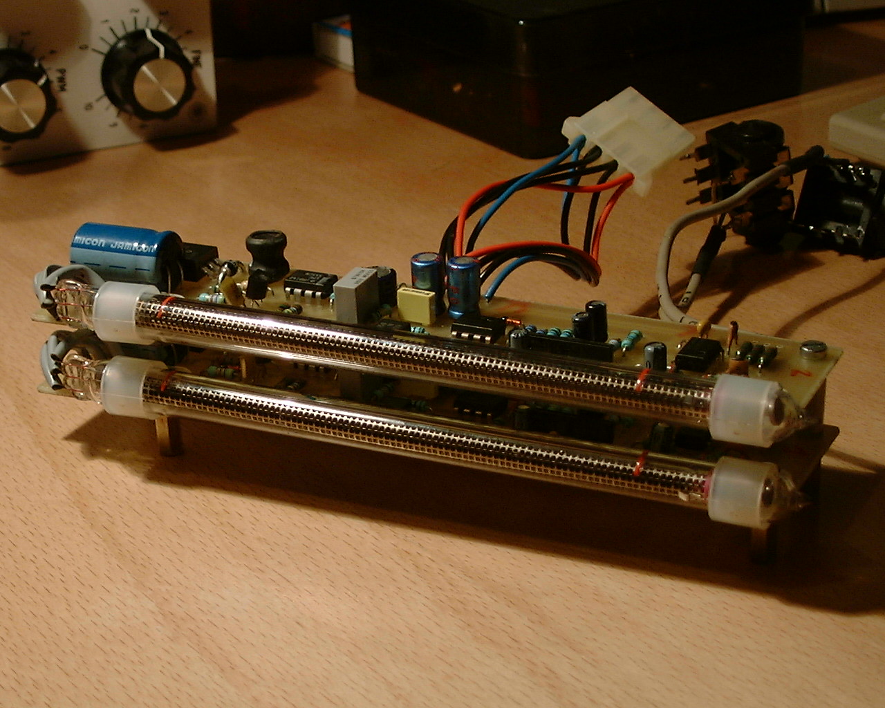
Here
is a stereo Vu-meter with IN-13 made with two rev 2.1 boards stacked...Ready
to work !

The
stereo version with IN-13 and revision 2.1 pcbs in action
on YouTube !
 
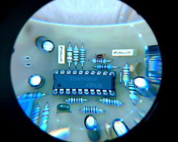
closer view ...
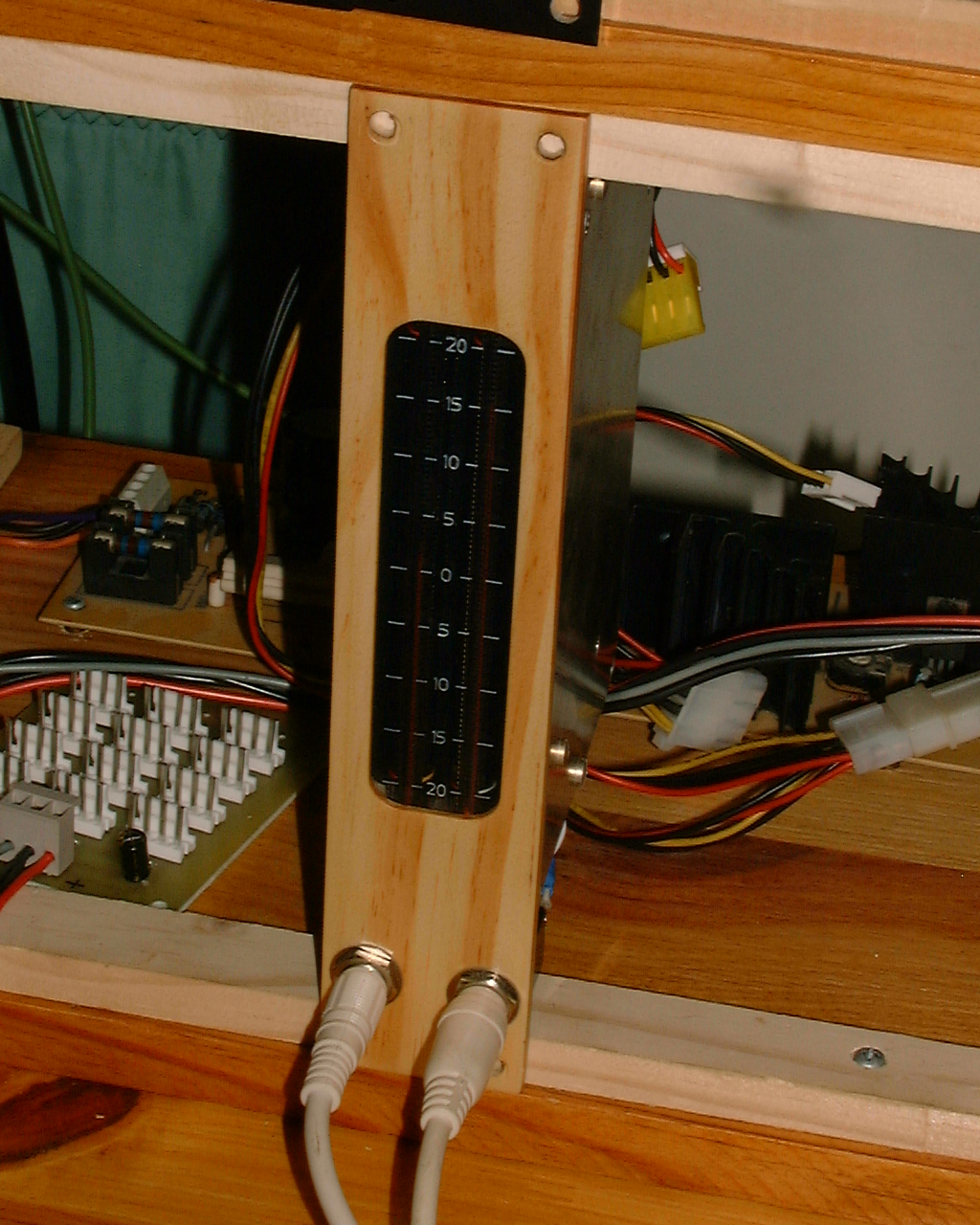
Plasma Vu meter +/-20dB stereo module
in 5U MOTM format
with engraved plexiglass scale and wood front panel /tube holder.
Wide Range 120dB Plasma VU meter - THAT4301
 The RMS detector of the VUmeter is based on THAT Corp. design note 119 . The RMS detector of the VUmeter is based on THAT Corp. design note 119 .
The IN13 driver and Hi voltage PSU are still the same.
Please notice that the Wide Range Vu-meter is not an 'upgrade' of the previous one. They do not have the same use in audio reccording .
The display range is 3 times wider but the db/mm resolution is also 3 times lower ! Not counting the compression factor of 2x of the RMS analyser stage.
It is just a different tool to display audio levels another way .
Features :
- unbalanced input
- -100dBU
to +20dBU range
- True RMS
Levels
- Adjustable 0dB point
- CV output
- Integrated
hi-voltage transformless PSU 150V/8mA
- Module powered
by +/-15V or +/-12
- Small pcb with 0.100" connectors
The THAT 4301 chip contribute to reduce the number of ICs ,so the pcb is smaller too.
Download
the Wide Range 120dB Plasma VU-Meter - final schematic (pdf )
Download
the Wide Range 120dB Plasma VU-Meter -BOM (pdf )

.
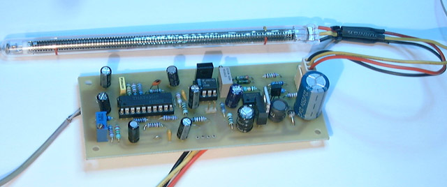
Picture of the first prototype
Here is a scale for this vu meter ...Not yet sure it is exact ;)
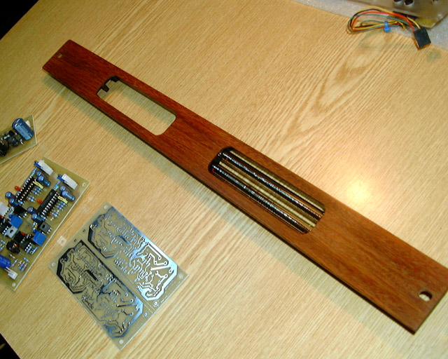
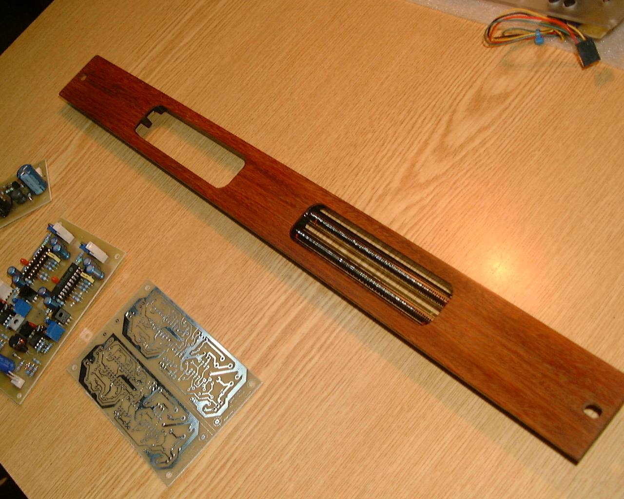
2x Stereo Wide Range Vu meter front panel made with teak wood and carnauba oil finish.
Format rack 19"-1U .
Vu meters pcbs ( in construction ) are at the bottom left of the picture ...more to come soon....
Multiband VU Meter projects
todo, coming soon :)
FAQ
-All
audio circuits are powered under +/-15V . To simplify the
integration of the VU meter into various devices, a high
voltage DC to DC converter has been included. It transform
the +15Vdc into a clean +150Vdc at approx 8mA. The high
voltage converter is a minimalistic switched psu based on
a 555 and a mosfet transistor. This cheap and secure solution
provide an independant power supply for each tubes. It is
ideal for multiples Vu-meters displays.
Please notice the plasma VU-meter pcb v2.1 integrated hi-voltage psu is only to drive IN-13 tubes. This psu is not powerful enough to drive IN-9 tubes !
-For IN-9 afficionados : The IN-9 require at least 12mA but many tubes need up to 50mA for tube pre-polarisation during a short time period to be able to reach the full range at 12mA ...However it is still possible to use the RMS detector+ tube driver holded by the pcb v2.1and to supply the IN-9 tube with a more powerful external hi-voltage psu. Be aware that 50mA is for one IN-9 tube so for a stereo version you will need at least 100mA under 140V dc ...
-To build an accurate VU-Meter the IN-13 is the best choice :
- It is very stabe
- it start glowing at the bottom of the tube
- it consume less curent : 5mA full range, ideal for multi-tracks displays
- it have increased length ...
-In normal use the IN13 tube do not heat
|