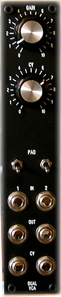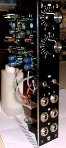
It is
a hi-quality audio VCA module designed with THAT2150A circuits.
Audio
Inputs work with synths levels as well as line levels. Level
"Pad" switches are provided to select input level/impedance
for best performances.The audio path is 100% dc coupled,
with an unusual but perfectly sounding coupling capacitors
stage. on audio outputs.
The expo
converter is integrated to the 2150 circuit. Just the scaled
CV paths and (optional) tempcos were added. The design has
been optimised for very fast and "clic-free" control
of VCAs.
CV inputs
range is 0 to +5V. At 0V on CVIN the VCA is closed ( approx
-100dB signal attenuation). With CVIN = +5V VCA gain is
1:1. and at CVIN =+7V the VCA gain is close to +20dB. Only
the VCA1 have control potentiometers : INIT GAIN and CV
IN attenuator. CV
inputs of both VCA are linked together, by the jacks preset
legs. It is an useful wiring tip to drive a stereo audio
source with one CV and one wire...
Audio
performances are excellent and much better than any common
synth VCA designs (ota,transistors..). The distortion amount
is low and trimmable (optional). The noise floor is somewhere
around -100db.
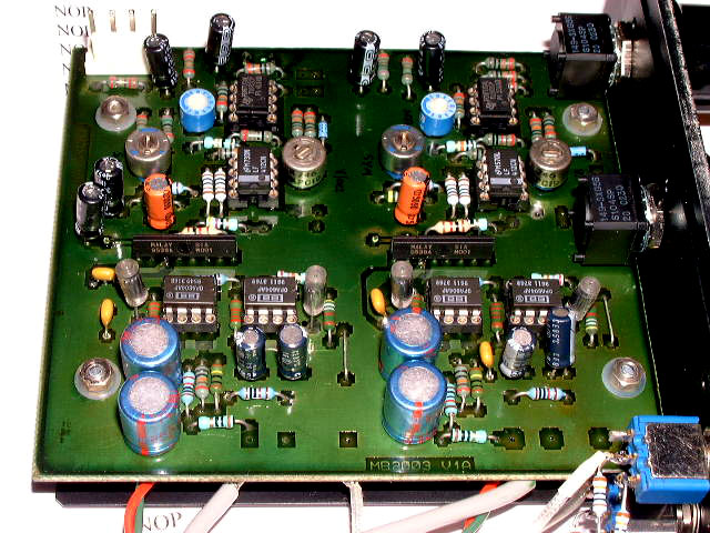
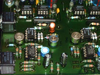
The green
double side pcb is homemade. It have a hi degree of symetry
. This is mostly for "stereo" applications of
this module ... The top layer has been varnished before
parts soldering, the solder layer has been painted after
final tests of the circuit.
Please
note : this schematic is in generic form ... this mean
"the pcb contain all possibility" but many parts
are not obviously required depending of what you plan
to do with this VCA.... Some values may be adapted too
and external wiring may occur, like with "pad "
switches : they are not represented on the schematic.
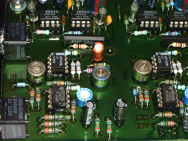
All audio amps gain resistors can be changed to fit any
level needs. The basic design is for NE5534 but if you
want to use other good quality aops you may remove or
add parts accordingly. My pictured prototype use OPA604
audio aops. At the audio output stages are "chemical
emulation of a fat unpolarized capacitor". This stage
give a unique color (available only in big studios with
very long mixing desks ;-) The pcb design allow other
kind of coupling capacitors stage to be implemented too.
The
2150 is driven with symetrical CV to avoid "clic"
or" tumbs" noise that may occur during extreme
variations ( a pulse square forexample). CV is calibrated
by a voltage divider with 1K+3300 tempco resistor ( fully
optional ). Else it is a quite common CV driver stage.
The zener diode is here to limit CV input range to reasonable
values. When the VCA is well tuned the full CV at the
2150 chip is around +/-310mV. Other circuitry around the
2150 chip are PSU and symetry trim. This small pot is
to improve distortion of the VCA core. The natural distortion
of the 2150 is very low compared to many other synth VCA
design. So this pot is for people who want accuracy and
have a spectrum analyser or a distortion meter at home
... There are more complex circuits possible for this,
but i believe they are not very important for this kind
of "musical "application. The sound quality
is already excellent! Trimless versions of the 2150 also
exist (2180) Then it will be easy to forget this trimpot
... For CV path aops , you can use almost anything ( TL072/74,
LM324, LF412., OP275... ) But it is better to keep a good
quality low drift , low noise noise one for the last driver
stage before the 2150....Well , in this schematic portion,
i do not advise to modify any resistor values if you do
not have any idea of what you do ...0.1% Precision resistors
increase performance and stability specialy here, but
again this is optional and for purist only !
The
THAT datasheet mention possibility to drive the 2150 with
dc voltages with minimal looses on ac signal. It is quite
easy to do with this pcb. Just to remove all serial caps
in the audio path and few resistors all around but i did
not try that yet ...
Dual-VCA
schematic PDF
Dual-VCA
front panel FPD file for the pictured 1x5U "
MOTM like" module.