-
To edit all Quantix-8 parameters with system exclusive messages
-
100% independant of the PC editor software, but still editable with...
-
8 memory locations to save/load parameter sets.
-
Recall memories by MIDI program change
-
Work with a +9V battery or a single psu
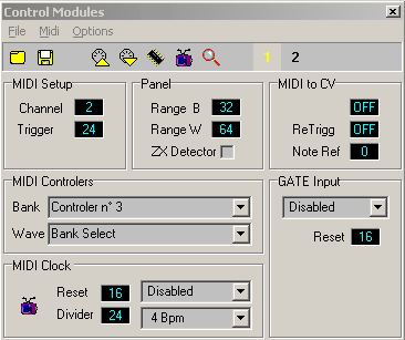
The Quantix-8 MRC is the hardware equivalent of the following dialog box of the PC editor software.
MIDI channel change and 'Send Write to Flash' buttons are implemented.
The Quantix-8 MRC receive system exclusive messages from the PC editor software; It is a very fast way to fill MRC's memories! The MRC is transparent for all other MIDI messages, on any channel. This include Quantix-8 wavetable sysex messages. MRC messages are merged with incoming ones.
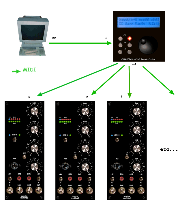
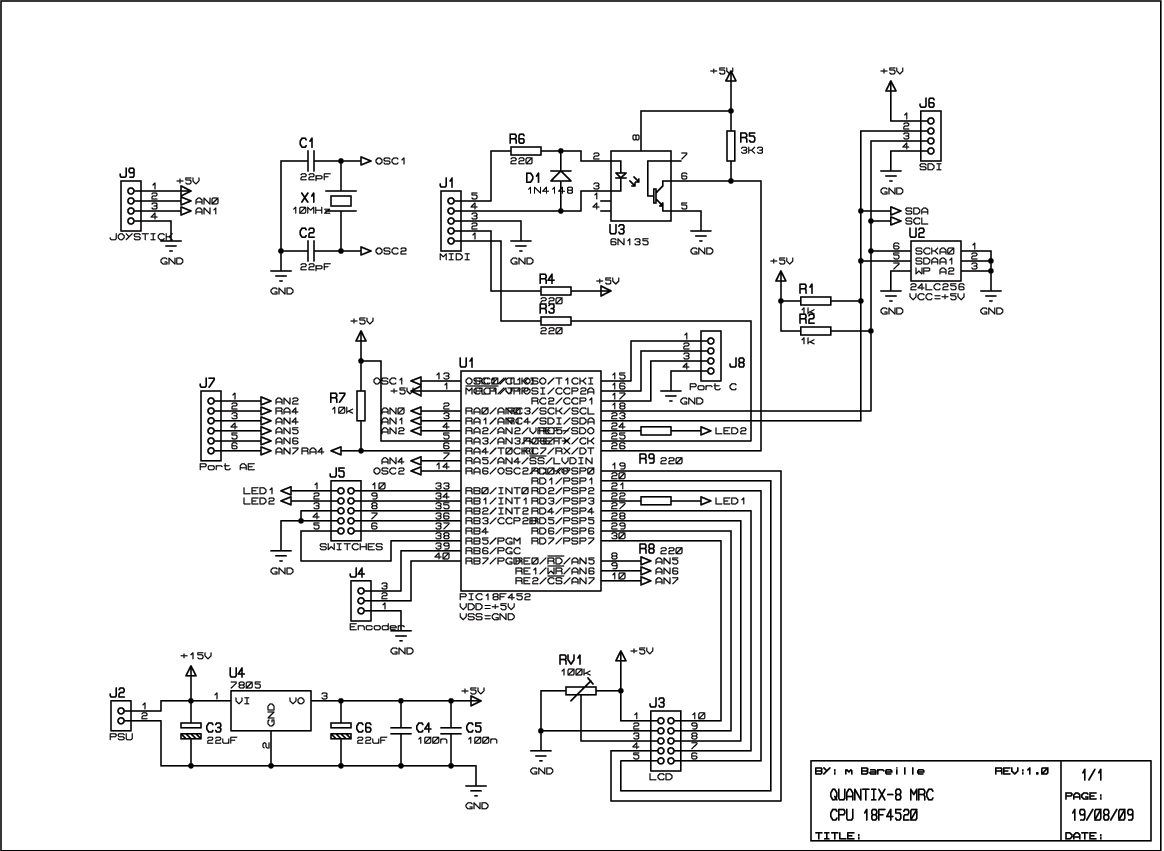
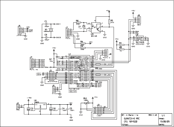
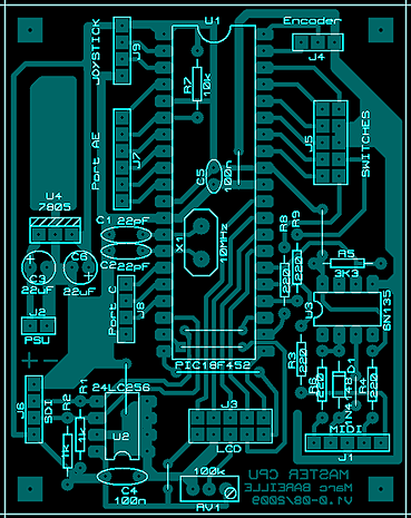
Schematic, pcb ...
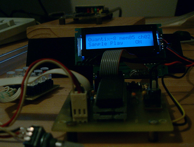
The module containa PIC18F4520, a standart 2x20 LCD display , 6 push buttons, one encoder, two leds and classic MIDI I/Os. The pot/trimmer RV1 is to adjust the LCD contrast as desired. There is also a serial eeprom (reserved for future use) and many connectors for free PIC I/Os . The power supply of the circtuit is +8Vdc up to 20Vdc-with an heatsink on the 7805...
Download the Quantix-8 MRC bill of materials (txt)
Clic to enlarge
Firmware
Download , unzip and burn this file into a PIC 18F4520 ...
Quantix-8 MRC firmware v1.0. HEX file for PIC 18F4520 (zip)
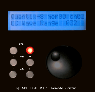
The parameter to edit is selected by center buttons.
To change parameter values there are bottom buttons ( inc = right, dec = left) or the optional encoder .
Top buttons are to access System and Memory modes .
When the System mode is activated ( top left button) : the center left button is to send a MIDI channel change message . The new MIDI channel value is displayed on the LCD and changed by the center right push buton -increase only ... Bottom push buttons are No( left) /Yes( right) to execute the order. Push the top or bottom left button to exit the system mode.
When the Memory mode is activated (top right button): . The red led stay light on. Center buttons are to select the memory location ( 0 to 7) . The top left button is to select LOAD or SAVE function. Bottom buttons are No/Yes to confirm write . Push again the top right button or the bottom left one to exit the Memory mode .
-
The System led blink briefly when a MIDI sysex message is received.
-
When datas are correctly writen to the Flash memory , the system led blink 3 times ..
-
The memory number 0 is automaticaly loaded by default when the MRC boot .