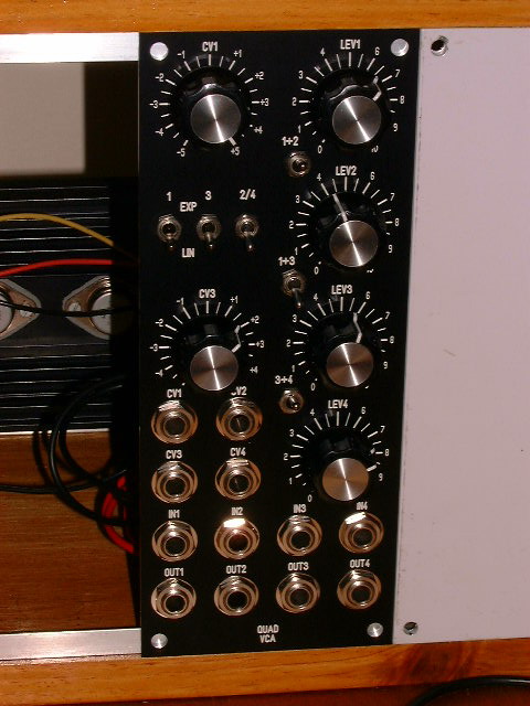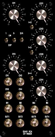
This
module is a hi-quality, all purpose Quad VCA/CV-Mixer.
VCA are very important modules for all modular and synths in general...This module contain 4 VCAs with Exp/Lin modes and switchable summing
stages on outputs. The Quad VCA
module work with audio signals and/or CVs ( no capacitors on I/Os).
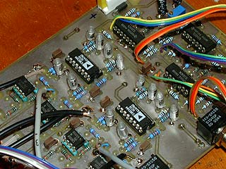
The
core of the Quad VCA is a pair of SSM2164 from Analog Device.
All 4 VCAs are independants and controled by 4 CV inputs
and "level" potentiometers.
Three switchable
summing stages are connected to VCAs outputs to allow any
internalcombination between VCA and CV-mixers ... So it
is possible to use this module as :
by
simply pushing few switches...
VCAs
1 and 3 are also fitted with reversible CV input attenuators.
Combined with output summing stages this module can be
used in a lot of various situations like :
-
cv-crossfaders
-
cv-panners
- cv-mixer+vcas...
- etc...
To
simplify paching operation, signal inputs are normaled as
follow IN1->IN2->IN3->IN4. All CV inputs are normaled
the same way. So with only one signal on input 1 , the Quad
VCA module become a :
Schematic
The schematic
of the QuadVCA is directly inspired by the work of Phillip
Gallo and the SSM2164 linearisation method proposed
by Mike Irwin on EDN issue. But i have choosen to implement
both CV circuits and to use a simple switch to select
them to control the VCA, instead of a relay. This solution
is finaly costless than to have to deal with 4 relays
on the pcb. Another advantage, there is no need of an
extra psu line for relays...The drawback it is this
solution is using more parts and half of them on the
CV path remain unused at any time ... It is a choice...
The QuadVCA/CV-Mixer psu is +/-15V but it will work
fine under +/-12V too

The Quad
VCA is made with a homemade double side pcb without metalized
holes ( soldering both sides ... ). Op-amps for CV controls
are TL074/84. Op-amps on the "audio" path should
be good quality ones , unlike what i did here :the prototype
is fitted with LM358 on pictures... .Something like OP275
, NE5532, OPA2604 will be good for this module ...
Note
: to keep identical performances for all 4 channels/VCAs
it is advised to use precision resistors ( 1% or better
) specialy for output opamps gain, and CV inputs ... There
are a lot of wires to solder for pots, switches and jacks.
They should be kept as short as possible. Shielded wire
are used for signal I/Os.
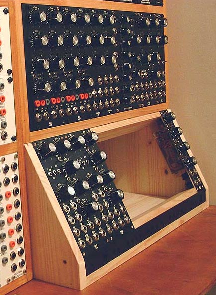
Front
panel
2x5U front panel
in MOTM format fit with 4 pots brackets, suggested panel
: Quad
VCA 5x2U Front Panel (fpd)
Clic
on pictures to view in big...
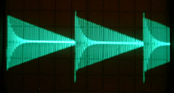
No
comment ... It sound good and work fine!
|