|
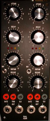
The Dual ADSR module
is adapted from the "EnvyLope" schematic of Mr Aaron
Cram. This
envelope generator design use the "J.Haible 4 transistors
core". It is a Linear Envelope Generator, with voltage
control. No OTA,CMOS, TTL,555, inside. 4 state leds shows
each step of the ADSR.
Unlike the original
schematic, my idea was to build a simple linear (CV) ADSR
module. Not a multimode beast ... So this version do not work
as an LFO, and CV control inputs are wired to potentiometers
only . No external CVIN, this will be for the next time !
It is rather easy to add anyway with an extra " pcb patch..."
Envelope outputs
are available on Jacks 6.35, direct (+) and inverse (-). The
"INV" switch is a to add offset to keep the inverse
(-) signal in positive domain.
The envelope output
level is internaly trimmable. There is also 3 trimers to setup
range times of stages A,D and R . They are not very obvious
to tune ... 10/25 turns stable cermets advised... Envelope
times are ranged from fast ( <5ms) to very long (> 3
mins).
Logic i/o are bananas
plugs. It is a personal choice , you can use jacks as well
...They are from left to rigth.
- GATE IN =
0/+5V standart with 2.5V threshold
- TRIGGER IN
= to reset the ADSR cycle at any time
- SUSTAIN GATE
OUT: output a positive gate
only when the ADSR is in sustain mode . Very
useful to link many envelopes for more complex
EG shapes.
Note :
If nothing is connected to the GATE/TRIG input " the
ADSR is Sustain Mode" : EG outputs send a dc voltage
set by the sustain knob. Act as a manual CV pot with direct
and inverse CV present at the EG output jacks ... The Sustain
Gate out is Hi level ...
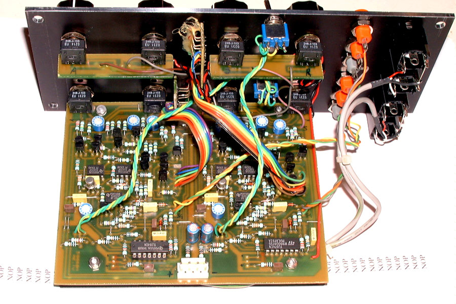
Schematic
Here are
changes i have applied on Aarons Cram's Envylope schematic:
- - removed
the exp mode
- -Gate/trig
in/out are now positive only ( range 0..+15V )
- - threshold
set at approx 2.5V ( it can be set to any value anyway..)
- -Add
output calibration stage and a reverse+offset output.
- -Add
Low impedance potentiometers voltage source.
- - modified
constant values in CV input paths.
- -Add
buffer to sustain CV input
The transistor
core work well enough even with unmatched transistors. I have
now builded 2 modules (= 4 EGs) , and tuned them to produce
quite similar time constants. They seem to be quite stable
... I have tested with matched and unmatched cores and the
difference is not really critical ...but i have finaly choose
to implement matched cores anyway ... I use BC550/560 for
transistors all coming from the same batch... TL072 and LM324
aops...

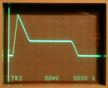
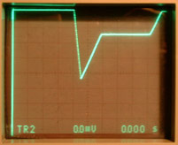
Here are scope
pictures of the Dual envelope outputs.
Note : on
the rigth it is the negative output signal without offset.The
scope offset this trace to be = 0V set to the top of the screen.
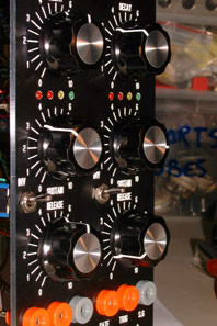
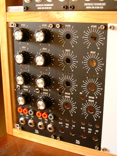
Front
Panel
-Dual
ASDR front panel FPD of pictured panels in Schaeffer
format...
Dual
Linear ADSR pcbs set + Construction Manual
are
available on order
|