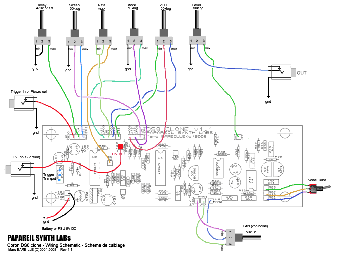
Here is the updated wiring diagram for the rev 1.1 board . Clic on the picture to view it full size...

There is now a pad named J102 ( R100) . It
is a CV input to modulate the VCO pitch by external voltage sources .
An attenuator pot can be added to this input. Notice this
CV input is not 1V/Oct but it will work fine with modulations
between 0..5V . It is also advised to add an attenuator
pot on this input ...
The
noise generator is a very classic design with a pair of
transistors. It is colored by a switchable 2 colors 1
opamp filter ( hi/lo)...It is simple to replace the switch
by a rotative selector and a set caps of different values
to get more "colors"...
The
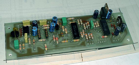
DS8 clone (prototype v1.0) at the end of assembly.

DS8 Builder's FAQ:
I often receive same questions about the DS8 construction so here are anwsers :
Q) What is R31 value ? What does 'NC' mean ?
A) R31 is marked as 'NC' ... NC mean = Not Connected ... forget this resistor ! Not used...
Q) What is R8 value ?
A) R8 value is 22k like the DS7 .
Q) The output level is low ... What can i do ?
A) The output level is sized to be around -10dBu nominal. To increase it : replace R30 ( 100k) by a 330k or 470k resistor . This should be enough for most of applications, including modular synthesizers patches ... Another solution: use a good preamp...
DS8
Sounds & video clips
As you can see, it sound similar to the DS7 buth with a noise generator ...
Here is the DS8 demo videoclip made by Djthomaswhite (UK) .

and another one with 6 x DS8 + mixer

Also search on You-Tube with the following keywords : 'Coron' , 'DS7' or 'DS8'
for more video clips .
Please visit the DS7/8
Picture Gallery too!
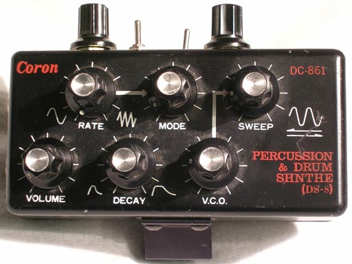
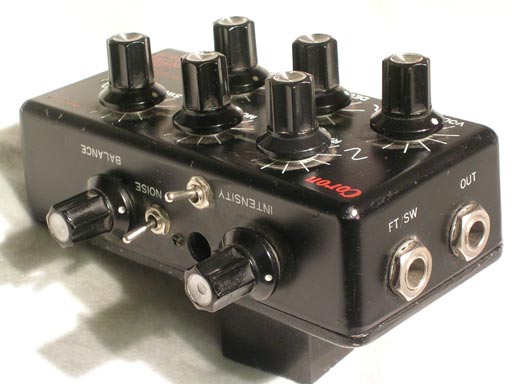
Thanks to Heiko for the vintage DS8 pictures


