Réalisation
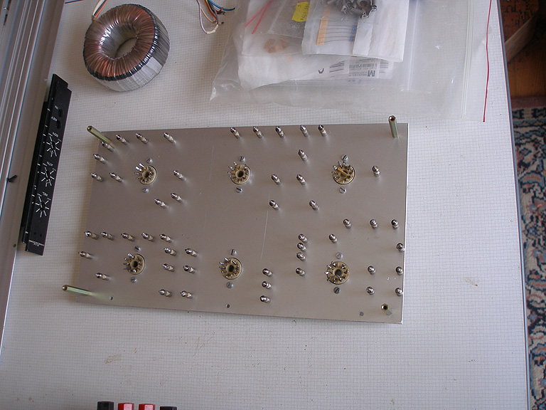
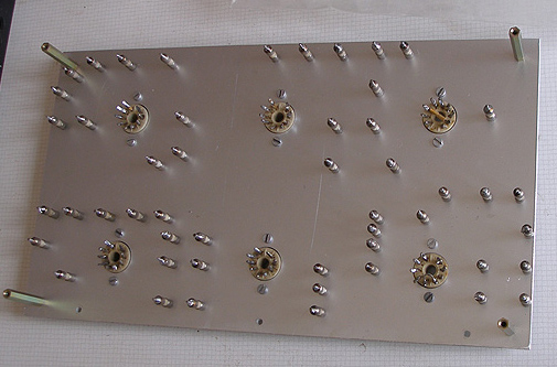
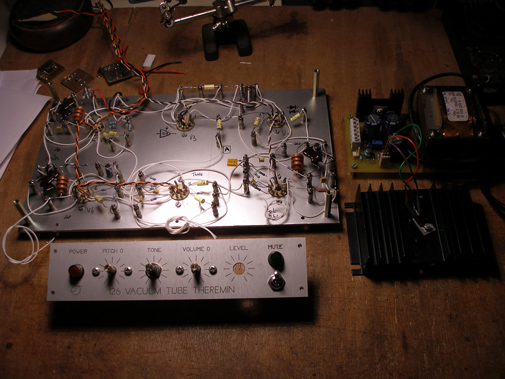
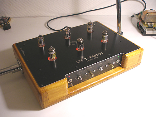
I folllowed the original schematic rev3 for parts disposal and assembly .
Parts are mount on vintage ceramic isolators and sockets !
clic on pictures for bigger resolution
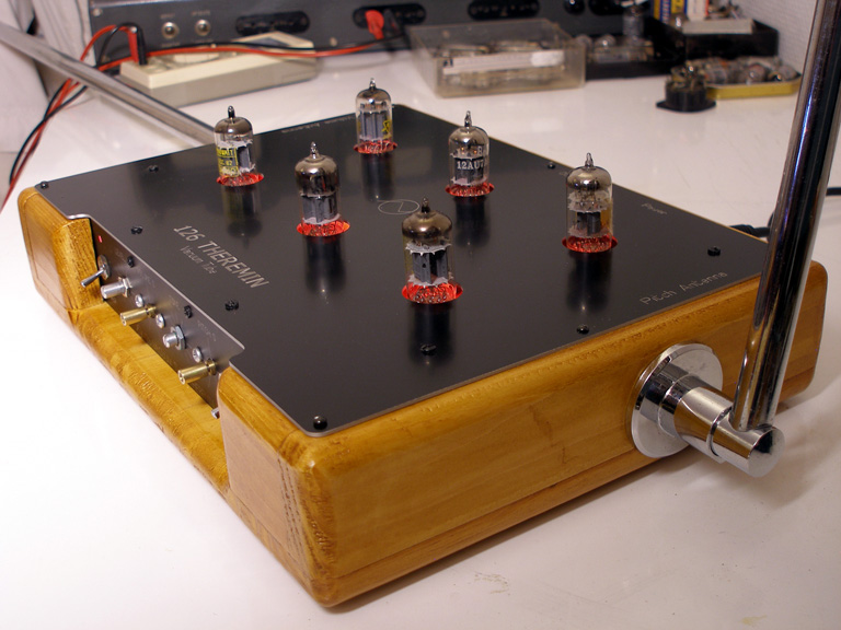
Complete wiring , with the custom psu on the right .Later I replaced the front panel by a black one for the final version.
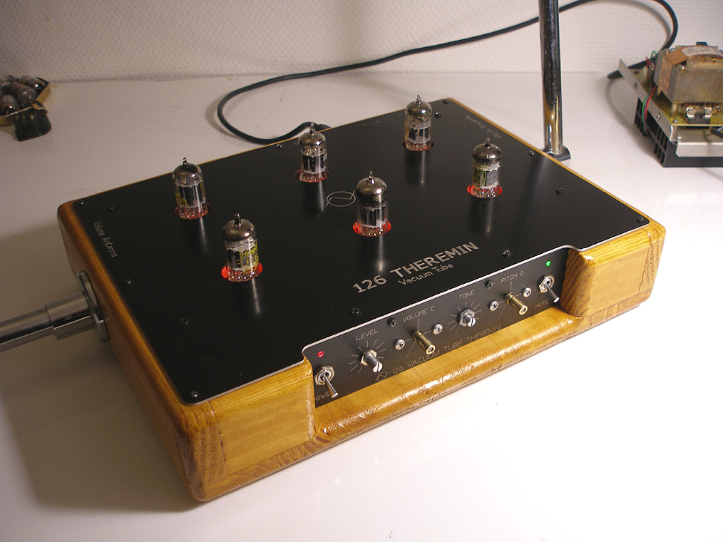
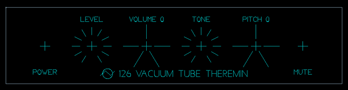
The front panel and the box
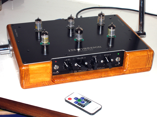
I added an output level control a two switches with leds .
The Mute switch is the volume antenna direction ( closer = full level Or closer = nosound position ) as decribed into the Rev 3 schematic . All front panels are laser engraved and cut/drill with the CNC machine on black painted or anodized aluminium .
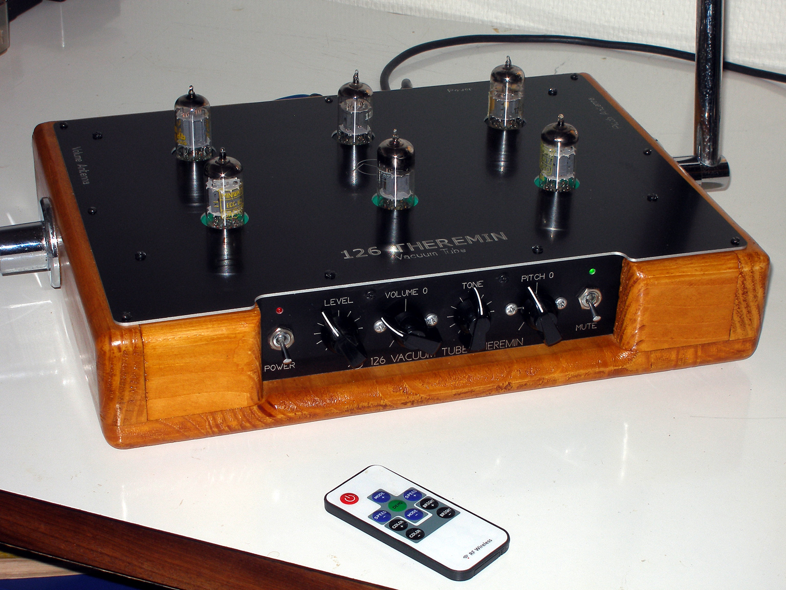
Antennas
It was the hardest part to find . I wanted removable tubes antennas. I ended with a chromed bar used to hold shower.... There are two 90° attachement with a screw in the middle to fix the socket on a wall and a little screw to lock the tube in place. It is very easy to mount /unmount antennas to carry the theremin.

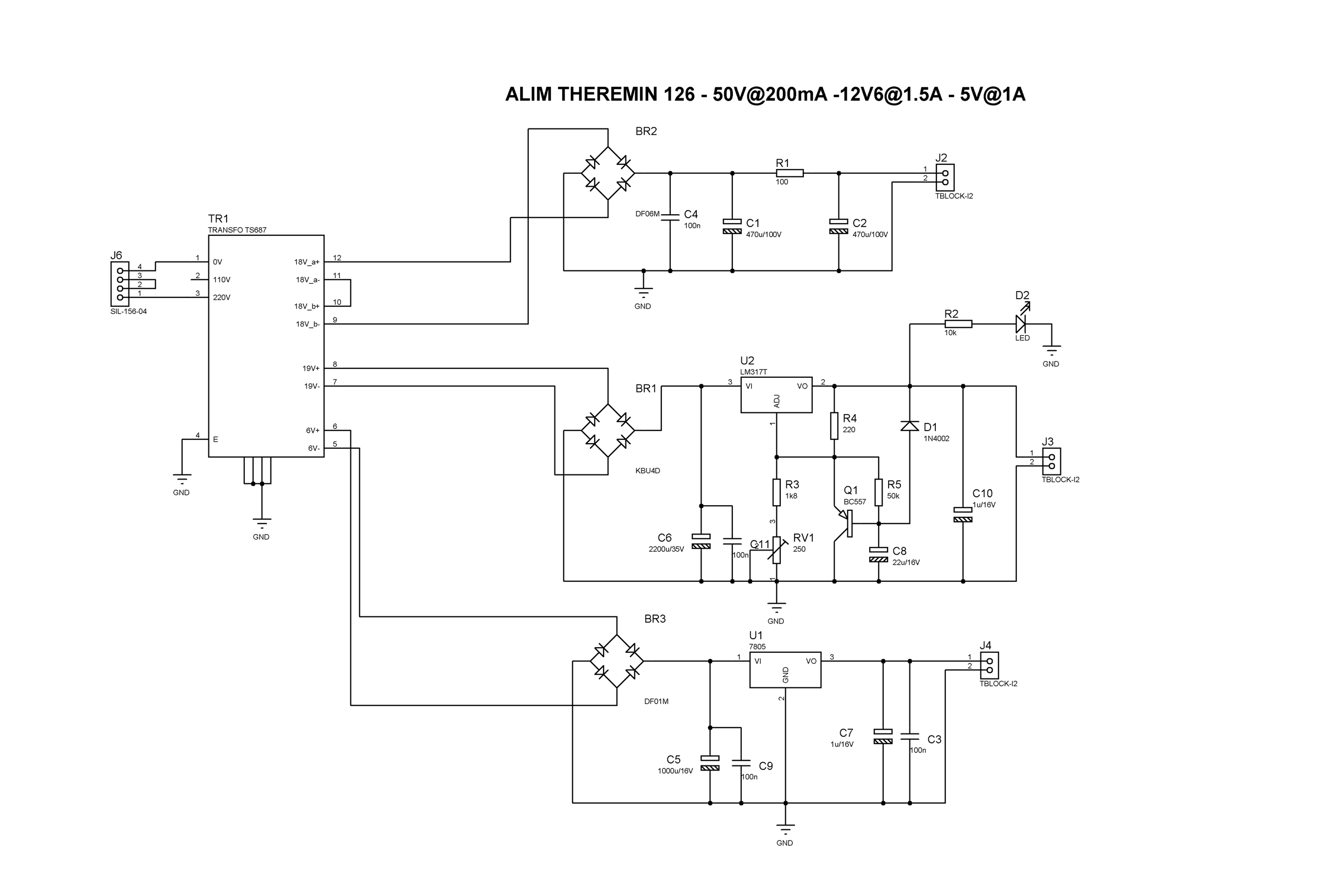
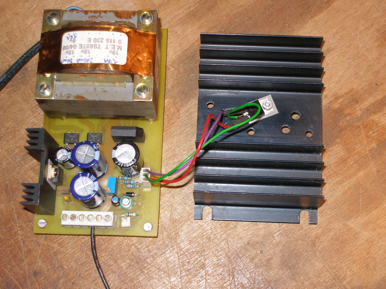
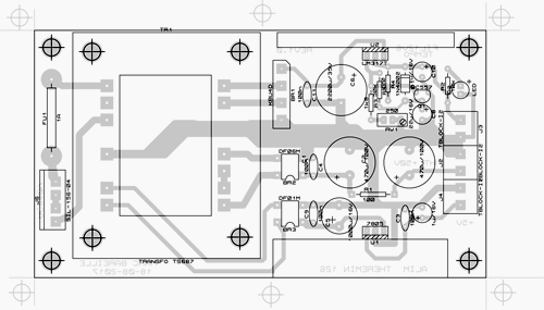
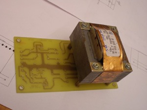
The Papareil's regulated PSU
I builded my own PSU to power the 126 Theremin. The psu provide 'hi' voltage of approx+50VDC for tubes plates , and 2A of +12.6V DC for tube heaters . I added a regulator to stabilize heaters voltages. It is not really necesary , but it is always better for tube lifetime and to get a better signal to noise ratio. There is also a regulated +5V auxiliary output for leds and other things(midi cv/gate ?) . The 126 theremin PSU is housed into a separate box.

Papareil's 126Theremin PSU BOM ( txt file)

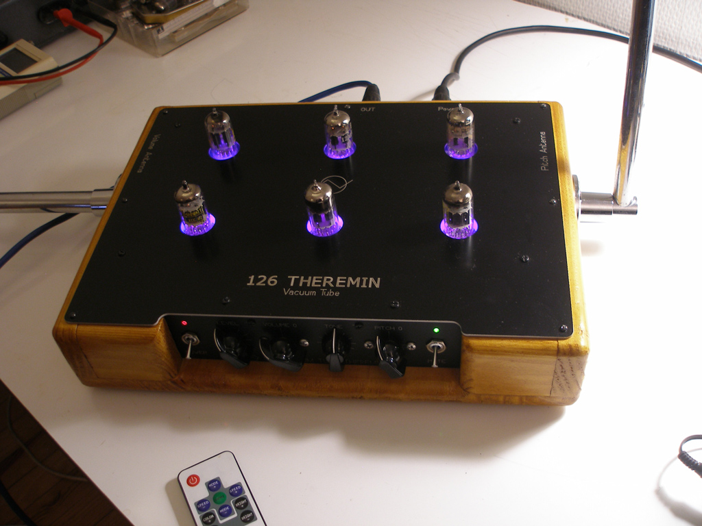
RGB Leds
To enlight tubes. I put an RGB LED ribbon under the front cover. They are powered by the 5V rail and fully independant of the rest of the cuircuit. only the ground is shared.
LEDs are driven by a radio frequency remote controler 468KHz . It do not interact with antennas.
The Sound
The 126 Theremin worked the first time i powered it . Pitch and level fixed oscillators running at their respective frequency without any adjustment . .I added a variable capacitor 10-60pF in parallel with C17 to get a coarse tune for the pitch oscillator. It is easy to set the antenna range this way.
Sound clips will come ,i only need a little bit of practice before reccording ...
The sound of the 126 Theremin is very good !
*
*
*