|
|
 The
MC628 is a converter to transform MIDI Clock [F8] messages
provided by any MIDI sequencer to an analog "pulse"
signal to send to Trigg/Pulse/clock inputs of analog sequencers,drumboxes,
modulars. The
MC628 is a converter to transform MIDI Clock [F8] messages
provided by any MIDI sequencer to an analog "pulse"
signal to send to Trigg/Pulse/clock inputs of analog sequencers,drumboxes,
modulars.
The cpu is a PIC16F628-20 microcontroler with a MIDI I/O interface.The
software encoded in the PIC is a MIDI clock divider from 1
to 255 . The PIC receive MIDI clock messages <F8> , count
them until a threshold value has been reached and if it is
the case, pulse a couple of pin (RA0,RA1). Note the clock
(+/-) provided by the interface is not a square (50% PW cycle)
signal , but a short pulse clock around 4 or 5 ms. I do not
calculate this precisely, just set it to the shortest working
value with all my test devices: a Korg SQ10, DS7
clone, the ASM1X... There is a delay time value in the code
to increase the length of the pulse, but i did not leave it
editable. Usualy the interface is set to deliver pulses from
1bpm ( or less) to 96 bpm. 4, 8,16 bpm are probably
the most used settings. The clock divider value is set with
MIDI exclusive message, also there is no need for knobs or
push buttons. An optional led give informations on the state
of the interface.
Schematic
& pcb
Clock outputs
are J1 pin 1 for Negative Pulse and J1 pin3 for
Positive Pulse. Other pins are free. The generic schematic
i drawn contains a lot of unused parts for this application
( J5,R4,R5 5) . It is possible to remove R6& R7 but the
RA4 port (pin10 of the PIC) must be connected to ground. It
is used for ISCP-LV programming ( see Microchip datasheet).
D1,R3 are fully optional If implemented the led ligth on when
a Midi Clock message or a SysEx message is received...Already
etched/drilled pcb are available , see end of page.
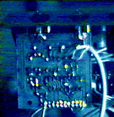
Download
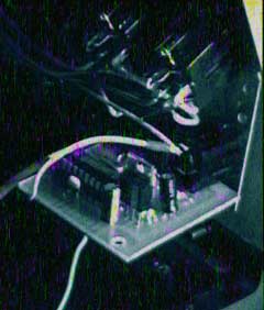
Inside the SQ10... a MC628 !
Firmware
for PIC16F628
It
is the main piece of code, the brain of the interface.
Download it into a PIC16F628 microcontoler. The file contain
all Config flags of the PIC. Do not change them. It is
possible to use low voltage ICSP to burn the PIC,
as the firmware was coded this way and leave free ICSP
pins ( RB6,7,4). Classic method for programming PICs work
also well.
Assembler
source code for the MidiClock628 v1.2
The
PC Config Software
The
MC628 memory is fully editable with MIDI exclusive messages.I
have written a complete MC628 editor/test software for
PC under Windows 9x/XP.This
software is freeware and is useful only with the MC628...
Download
"MC 628 config software V1.1" for PC ( 1.1Mb)
It is also possible
to send MIDI exclusive messages with a MIDI sequencer or any
device able to do that ... Here is a file who describe sysex
messages calculations to send to the MC628 to setup the MIDI
clock divider (1 to 255)
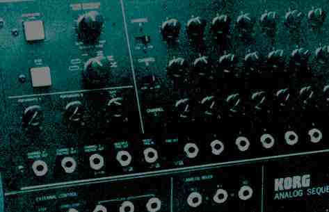
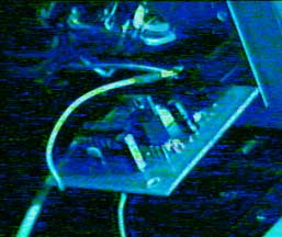
Korg SQ10
and MC628
Here
are pictures of the MC628 installed in a Korg SQ10 analog
sequencer to make it MIDI synchronisable with any MIDI sequencers.
This is an example... The MC628 can be used with many others
analog sequencers or drumboxes.
Download
Wiring draw of the MC628 inside a Korg SQ10
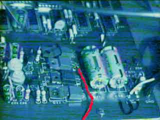
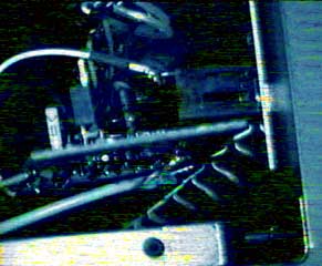
The
Pulse out of the MC628 is wired to the External STEP jack
input of the SQ10. The + psu is drained from the 7815 ( pin
1 -input ) on the SQ10 mainboard. ( red wire on the psu picture)
.The ground is connected to jacks STEP and START/STOP jacks
ground pins, by the MC628 pcb directly soldered to them. (see
pictures). As it is a small pcb, there is no mechanical problems
and no more hole to drill than the MIDI plug. It is the great
advantage of this "upgrade" , also fully reversible
and wired in less than an hour ! Now there is a minor drawback
to this simple method of : To drive a Korg MS10/20 with the
SQ10 in MIDI sync mode, the GATE signal must be plugged to
the SQ10 External STEP Jack - this input is now an output...
because the SQ10 "Multi trig " output provide now
a too short pulse to drive correctly the MS10/20 envelope.
|
|

