IMPORTANT
Notes :
- The ICSP
jumper J3 is not implemented forget it .
- U7
must be mounted on solder side missing space upside, so
take care to respect the 7808 orientation
- Use
only TO220 regulators . do not use TO92 ones !
- There
is 3 strap wire to solder on this pcb ... Do not forget
them!
- The
jumper JP1 must be set on . You can also solder a strap
here . Leave JP2 and JP3 open.
- U1
is a 7407 ... It is also possible to use a 7406 but then
config bits must be reversed in the hardware config page
of ICPROG or WinPIC
Power
supply must be at least 14V DC or a bit more !!!
How to use
it :
The prommer
must be connected to the paralllel port of the PC computer
with a DB25/DB25 cable.
Use ICPROG 1.05 with the hardware config setup as shown
below.
Note :
If ICPROG v1.04 is used , the programmer combo box
must be set on "TAIT parallel programmer " because
of a bug in ICPROG 1.04...
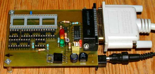
About onboard
leds :
Green led
ON = all is OK , you can insert a PIC on any socket
Yellow led ON = the VPON ( voltage for programming ) is
activated
RED Led ON = the PIC chip is powered , Do not insert a
PIC chip if red led activated

